DOD Grindhaus: a fuzz mystery
I recently saw someone post on a pedalboard group on Facebook a photo of a Dod pedal I’d never seen. The dod Grindhäus. Theres lots of theories about this pedal floating around but all we really know is a number of prototypes were made and liberated from the garbage. A few of these prototypes had been sold and exist out in the world (I don’t have one though so if you’d like to sell me one to help with this project, do send me an email).
I looked on the Dod pedal group and about a year back someone had posted a few photos of the pcbs. The pcbs themselves are two boards stacked, one holding all the knobs and another holding all the other circuitry as well as the footswitch.
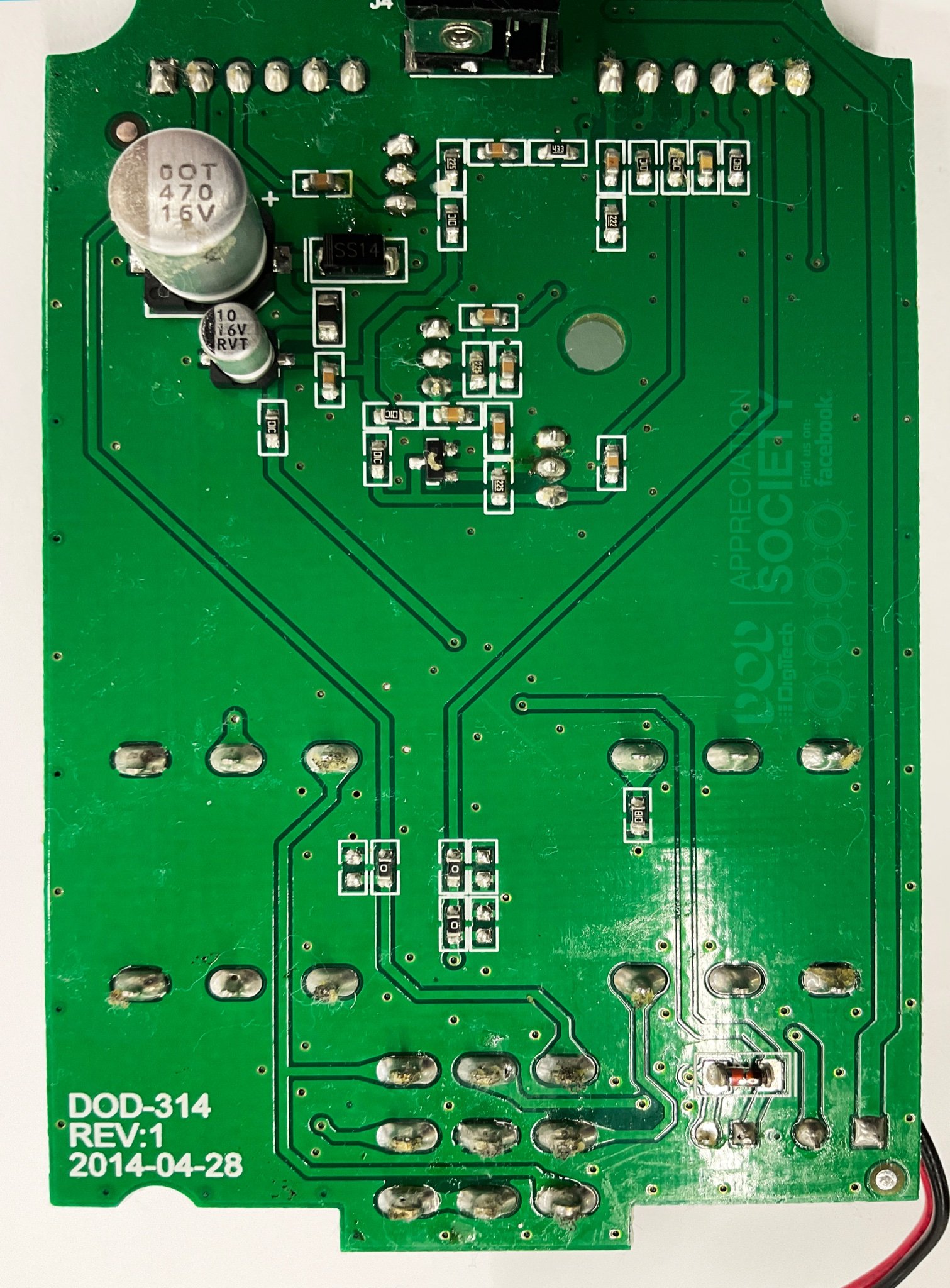
The big kick in the teeth at this stage is that it is all surface mount. This makes it much harder to trace not because of the size but because smt capacitors don’t have values on them. While three of the four transistors were through hole and easy to tell what they are, there was one transistor which was surface mount. The code on that was also obscured by either some pen or some dust or something in the photos. Knowing all this I pressed on and traced it anyway and will come back to what this transistor is and the values of these capacitors at a later date.
I spent an hour or so on a train slowly tracing the whole circuit. The resistors had readable values but with no capacitor values I needed some more information. If I had the pedal in front of me then I would have measured the values myself but the best way forward was to figure out if its based on anything. in the world of fuzz pedals a lot of new designs are just better or different versions of something old (at least thats been my experience anyway). Its pretty cool to see the improvements that have been made over the years.
So here’s the trace I had.
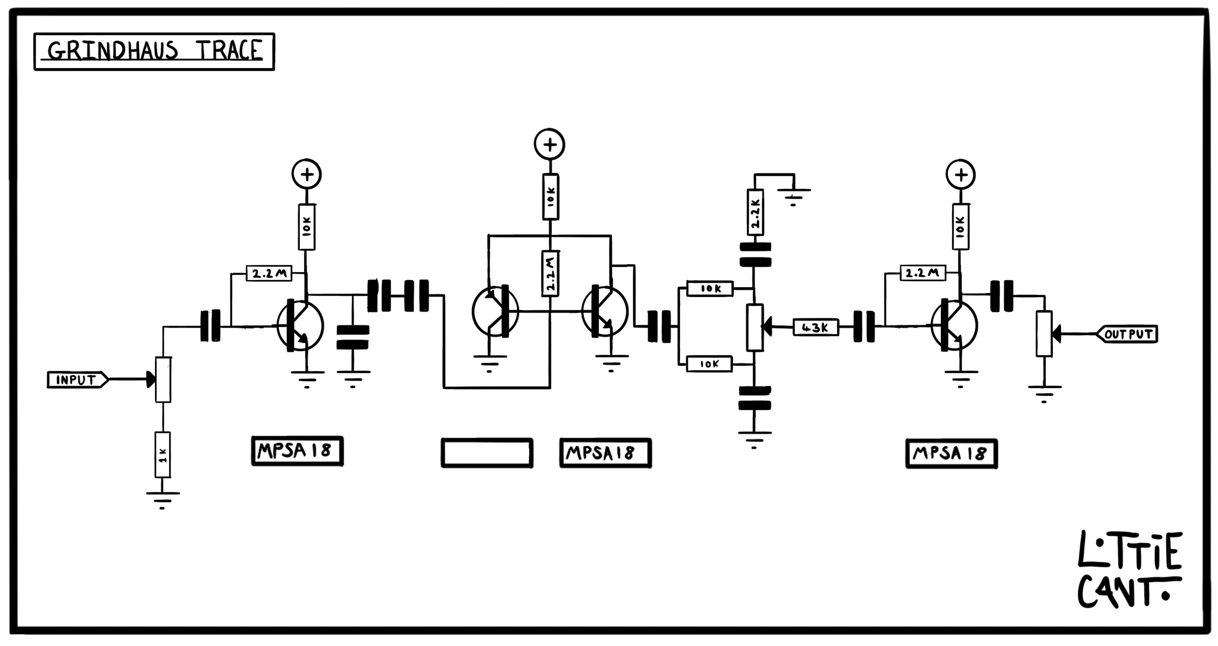

Mystery solved! (sort of)
knew I recognised the circuit as it has a few quite distinct parts. Firstly the two back to back pnp and npn transistors. The only fuzz that sprang to mind here was the old superfuzz schematic but this was a dead end since that was really the only similarity.
The other thing I noticed was the two capacitors in series. This is an unusual thing to see since these two capacitors in this configuration can be replaced with one by using this formula above.
This was the really big clue that this had come from somewhere. It took me a few days but I finally remembered that some of Devi Evers fuzz circuits had two capacitors in series ( I think it was something to do with multiple different fuzzes being built on the same pcbs).
So after a quick look through the archives of Devi’s circuits I found the one. The Devi Ever Hyperion was part for part identical to the first half of the Grindhaus (according to the resistor values I had) with the same transistors too. This is great news as it also tells us what that unknown transistor value is and also the value of those capacitors.

The rest of the circuit
The next section after the Hyperion is a tone circuit which ill come back to. Then at the end, another gain stage. This looks identical to the first gain stage of the Hyperion so I plumbed in those values there too.
from speaking to the owner of the pedal that had posted the shots of the circuit board (shout out to Buck Nerkerd on the DOD pedal group. This has kept me entertained for a while), he gave me the values of the potentiometers. The only surprising one was the gain pot which was a 1M instead of 100k like the Hyperion. The volume and tone were both 100k.
Tone section
The only thing we are left not knowing at this stage is the value of the two capacitors in the tone section. This is unfortunately where we hit a bit of a dead end. The tone section however is kind of interesting. At first glance it looks like a big muff tone stack where you have a high pass and a low pass filter that you sweep between, weirdly though this is more set up as two low pass filters. I was convinced I’d traced it wrong (and theres still a possibility of that) but I couldn’t seem to figure this out from just looking at it.
at this stage though we do have enough information to build the circuit up on a breadboard and figure out some capacitor values that might work in the tone section. At the time of writing this I’ve built one up and started trying a few values but I think its about time to open this up to the DIY community and everyone can come up with their own cap values. i’ve designed a pcb and will socket those and come up with my values. (I’ll order some extras in case anyone else would like to join me on the tone quest.

Above is the full schematic as I have traced it (apart from the power filtering section which was just a few filter caps and a diode). If anyone has any corrections or notes or any more information than I have please don’t hesitate to email or message me on instagram and i’ll update this page. Happy tone hunting folks!